The mutual coupling performance of the proposed two-element MIMO antenna was analyzed using surface current distribution. First, a slot was introduced into the radiator and rotated 45° clockwise. The current distribution on the surface of the proposed design is shown in Figure 2. When port 1 is energized, port 2 is terminated with a 50 Ω load. As shown in Figure 2a, more coupling between the two radiators was observed for the linear element array. However, when we introduce slots in the radiating elements and rotate each element by 45°, as shown in Figure 2b, a significant reduction in surface current is observed, resulting in mutual coupling losses with adjacent patches. did.

Surface current distribution at 29 GHz (be) straight element MIMO antenna and (b) Proposed elemental MIMO antenna.
Figure 3a shows the simulated electric field distribution at 29 GHz. Antenna 1 is shown to be excited while antenna 2 is connected to a 50 Ω load. The electric field distribution shows that the entire length of the antenna patch is responsible for the radiation. In the E plane, the mutual coupling is in TM mode. For further clarity, a simulation of the magnetic field distribution at 29 GHz is shown in Fig. 3b. A high current density is observed around the antenna slit, indicating low mutual coupling between the radiating elements. For magnetic fields, TE modes are observed. TM occurs when a square patch antenna is excited diagonally.01 and T.M.Ten Modes with equal amplitude and phase.

(be) electric field distribution and (b) H-field distribution for a reported MIMO antenna design at 29 GHz.
The scattering parameters of a linear element MIMO antenna are shown in Figure 4a. This array has a reflection coefficient (S11) -35dB. His two elements of the antenna are rotated 45° clockwise. This shifts the resonance to 31 GHz and the separation is − 15.5 dB, as shown in Figure 4b. Slots in the radiator or ground plane increase the effective inductance of the antenna, while capacitance is negatively correlated with slot width.3. Therefore, by etching slots into the radiator, the resonant frequency is reduced to 29 GHz. As seen in Fig. 4c, compared to the linear element design, the proposed design achieved −20 dB improvement in mutual coupling. Stwenty one At a resonant frequency of 29 GHz, it changed to -36 dB.
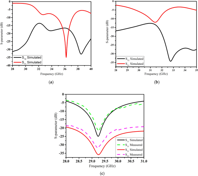
(S-parameter of)be) Linear element (b) bending element (c) and the proposed elemental MIMO antenna.
The scattering parameters of the presented MIMO antenna were measured in an anechoic chamber. Satisfactory results were observed in both simulation and measurement results, as shown in Figure 4c. The measured impedance bandwidth is over 1 GHz, which is sufficient for 5G communication devices. Similarly, the measured Stwenty one It was less than -32 dB at the resonant frequency.
A close agreement between the measured and simulated radiation patterns was observed, as shown in Fig. 5a,b. The radiation pattern was measured with one port excited with a 50 Ω feed and the second port terminated with a matched load. According to measurements, maximum gains of 6 and 5 dBi were observed in the E (xz) and H (yz) planes. The radiation pattern of the proposed antenna has very low backlobe radiation, which increases its effectiveness for future applications. The three-dimensional (3D) radiation patterns of the linear element MIMO antenna for 29 GHz and the proposed MIMO antenna are shown in Fig. 6a,b, respectively. High-side lobes and back lobes were observed for straight-element MIMO antennas. However, by introducing slots in the radiation patch, the main beam is directed towards a specific boresight direction with minimum sidelobes and backlobes, making the proposed design efficient for his 5G communication.
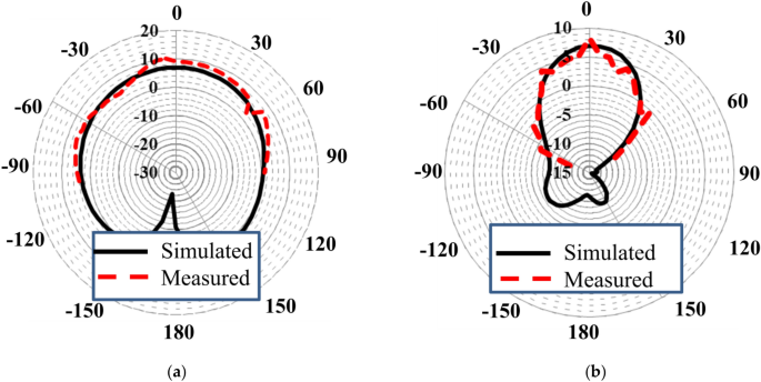
The radiation pattern of (be) E plane and (b) H side.
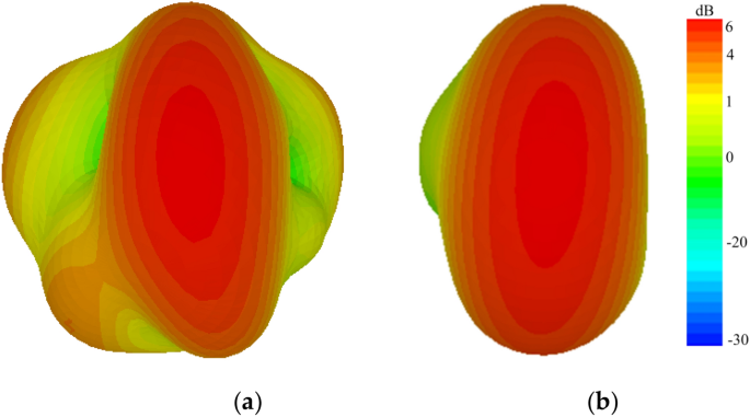
3D radiation pattern (be) Simple MIMO antenna (b) Proposed MIMO antenna.
To verify the compatibility, performance, and efficiency of the proposed mmWave MIMO antenna, the envelope correlation coefficient (ECC) was investigated. ECC is the relationship between the received signals at the ports of an antenna and requires calculating the channel quality for uncorrelated channels. A high ECC value results in high correlation and minimal separation, resulting in poor antenna performance. Additionally, ECC indicates the interaction effect of the overall S-parameters of the designed MIMO antenna. ECC can be found using different approaches: using the received signal envelope, or using S-parameters or far-field radiation to estimate the complex cross-correlation. In this paper, ECC is calculated using both S-parameter and far-field radiation pattern methods, as shown in Equations 1, 2, and 3. (3) and (4) respectivelytwenty four. On the other hand, in measurements, his ECC from the radiation pattern requires time-consuming integral calculations. To facilitate the measurement process, the ECC value of the proposed MIMO antenna system was calculated based on the S-parameters using Equation (1). (3)
$$ECC=\frac{{\left|{S}_{ii}*{S}_{ij}+{S}_{ji}*{S}_{jj}\right|}^{2} }{\left(1-{\left|{S}_{ii}\right|}^{2}-{\left|{S}_{ji}\right|}^{2}\right)\ left(1-{\left|{S}_{jj}\right|}^{2}-{\left|{S}_{ji}\right|}^{2}\right)}$$
(3)
$$\rho_{ij} = \frac{{\left| {\int {\int_{0}^{4\pi } {\left[ {\overrightarrow {{F_{i} }} \left( {\theta, \upphi } \right) \times \overrightarrow {{F_{j} }} \left( {\theta, \upphi } \right)d\Omega } \right]} } } \right|^{2} }}{{\int {\int_{0}^{4\pi } {\left| {\overrightarrow {{F_{i} }} \left( {\theta, \upphi } \right)} \right|^{2} d\Omega } } \int {\int_{0}^{4\pi } {\left| {\overrightarrow {{F_{j} }} \left ( {\theta, \upphi } \right)} \right|^{2} d\Omega } }}$$
(Four)
where, \({\uprho }_{{{\text{ij}}}}\)represents ECC. \(\overrightarrow {{{\text{F}}_{{\text{i}}} }} \left( {\uptheta ,\upphi } \right)\) and \(\overrightarrow {{{\text{F}}_{{\text{j}}} }} \left( {\uptheta ,\upphi } \right)\) are the radiation patterns of the i-th and j-th elements of the MIMO antenna. Here, I, j = 1, 2 in the proposed design.
The radiation efficiency of the MIMO antenna for linear elements, bent element arrays, and the proposed elements is shown in Figure 7. His proposed MIMO antenna achieves a radiation efficiency of more than 85% over the entire operating band. Ideally, the ECC value should be zero. However, in practice, uncorrelated MIMO adopts the ECC < 0.5 restriction.twenty five. Figure 8 shows that the ECC value of the proposed MIMO antenna is 0.0001 in the desired band of 29 GHz, which is quite close to zero.
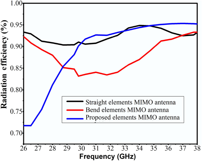
We simulated the radiation efficiency of MIMO antennas with straight elements, bent elements, and the proposed element.
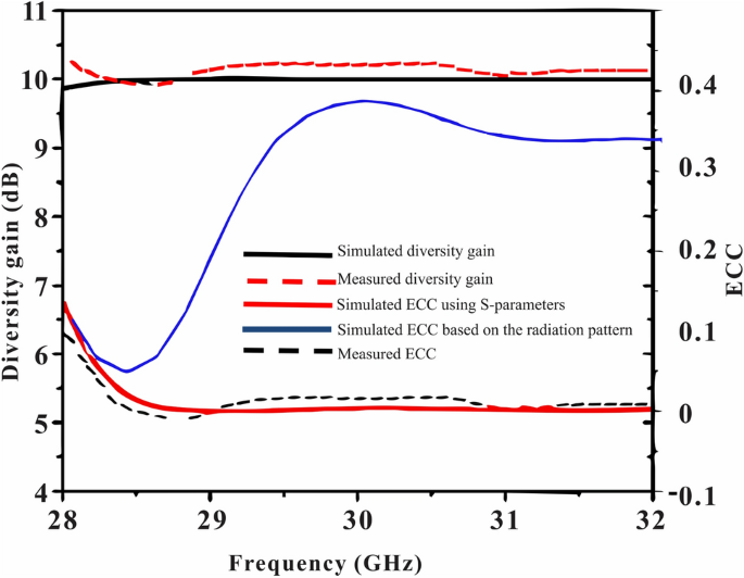
We simulated and measured the ECC and diversity gain of the proposed antenna.
Diversity gain (DG) is also an important parameter that must be considered when evaluating the performance of MIMO antennas. This parameter indicates the reliability of the MIMO system.High DG antenna systems have higher radiator isolation26. To calculate the DG of a MIMO antenna, you can use the following relationship:
$$DG=10\sqrt{1-{\left(ECC\right)}^{2}}$$
(Five)
The diversity gain (DG) of the presented MIMO antenna is shown in Figure 8 over the frequency range. The presented antenna has DG > 9.8 dB over the entire operating band.
Figure 9 shows the multiplexing efficiency and peak gain at different frequencies. Multiplexing efficiency (ηMax) is calculated using the following relationship:
$${\eta }_{Mux}=\sqrt{1-{\left|{\rho }_{c}\right|}^{2}{\eta }_{1}{\eta }_{ 2}}$$
(6)
where ‘\({\uprho }_{\mathrm{c}}\)‘ is the complex correlation coefficient between antenna patches. \(\mathrm{ECC}\about {\left|{\uprho }_{\mathrm{c}}\right|}^{2}\)and \({\upeta }_{\mathrm{i}}\) is the overall efficiency I-th antenna radiator. I used i = 1, 2 because here I have her MIMO array of 2 elements.
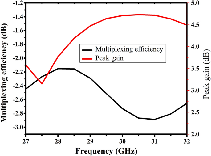
Simulated peak gain and multiplexing efficiency of reported MIMO antennas.
Table 1 shows a comparison between the proposed one and some recently published works based on various performance characteristics.in27proposed a millimeter-wave eight-element MIMO antenna array using beam tilting and highly isolated dielectric resonators. 25 dB minimum isolation and 7 dBi peak gain were achieved at the expense of large size and manufacturing complexity. Similarly, the Yagi-Uda antenna for millimeter-wave MIMO terminals is28, an excellent isolation of 21 dB was achieved in the proposed design. Horn-shaped vias were used to enhance isolation. Metasurface-based waveforms were used to reduce mutual coupling.29, and an excellent isolation of 37.1 dB was observed at the desired center frequency of 28 GHz. However, this design requires a complex manufacturing process. Similarly,30The 4-port MIMO antenna is designed for mmWave applications and provides better impedance bandwidth while achieving only 21 dB of isolation in its wide dimensions of 48 x 31 mm.2.in31, a quad-element MIMO antenna is proposed for UWB applications. By using parasitic elements, isolation is improved by 20 dB.in32a four-element MIMO antenna operating from 23 to 28 GHz is proposed, and the isolation is improved by using a defective ground plane.
The proposed MIMO antenna maintains a compact structure of 11.7 x 5.3 mm2, through the use of slotted and tilted antenna radiators. Excellent isolation of 36 dB, low ECC value of 0.0001, and high diversity gain of > 9.8 dB were achieved. Both measurement and simulation results were found to be in close agreement, making the proposed design a strong candidate for his 5G mmWave communications. Slight differences between measured and simulated results are due to manufacturing tolerances.


